Intelligent flow control valve
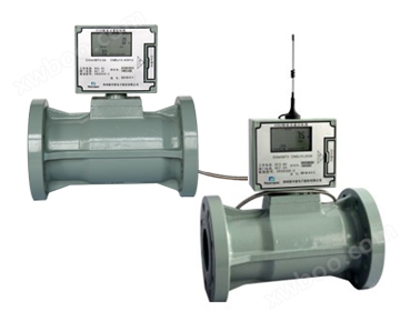
The R208 series intelligent flow control valve is a new type of intelligent flow control instrument that combines IC card flow control valve and remote monitoring. It is an intelligent control system that integrates various services such as prepayment, valve control, remote monitoring, data acquisition, and automatic meter reading.
function and characteristic
- Prepaid and automatic billing functions, accurate data; Prepaid payment method: Gas volume and amount billing methods are optional;
- Data communication and remote meter reading function, accurate data collection, can supply power to various flow meters and communicate with each other;
- Strong compatibility and scalability, compatible with any manufacturer and various specifications of flow meters/diaphragm meters;
- Power failure, no gas, anti magnetic, anti shear, and anti leakage monitoring functions; When there is magnetic interference or illegal operation, the valve will automatically close and cut off the gas pipeline, facilitating the gas company's gas management;
- Abnormal alarm: Report to the backend monitoring and management system in a timely and proactive manner.
Main technical parameters
Control valves are widely used in media such as natural gas, coal gas, liquefied gas, etc., and are compatible with different specifications of flow meters (industrial measuring instruments). By connecting with the flowmeter through a data cable and using GPRS network communication, accurate and real-time data information such as cumulative usage, instantaneous flow rate, and operating status of the flowmeter is collected and transmitted, and uploaded to the data center at set time intervals. The data center can analyze and track various user data, thereby improving the management level and service quality of the gas company.
The control valve, in conjunction with the prepaid management system and remote monitoring system, achieves scientific management of pipeline gas usage control and remote real-time monitoring, meeting various needs for flow meter automation and prepaid management, effectively solving problems such as difficult charging and control for gas companies, and providing convenient and efficient management methods for gas companies.
Specific functions and features
- Prepaid and automatic billing functions, accurate data.
- Prepaid method: Gas volume and amount billing methods are optional.
- The standard volume corresponding to a unit pulse can be set, and different pulse signals can be measured.
- Data communication and remote meter reading function, accurate data collection, can supply power to various flow meters and communicate with each other.
- Strong compatibility and scalability, compatible with any manufacturer and various specifications of flow meters/diaphragm meters.
- Real time monitoring of flow meter operation data and on-site status, and uploading to the data center.
- Power failure, no gas, anti magnetic, anti shear, and anti leakage monitoring functions. When there is magnetic interference or illegal operation, the valve will automatically close and cut off the gas pipeline, facilitating the gas company's gas management.
- Abnormal alarm: Report to the backend monitoring and management system in a timely and proactive manner.
- Remote monitoring of valve switches, with the initiative in the gas supply side and low operating costs.
- Large screen LCD display, visually displaying various data and status.
- Multiple power supply methods, supporting mains electricity, solar energy, and lithium batteries.
- High performance low-power processors and special peripheral circuit designs ensure long-term reliable operation.
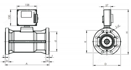
External dimensions:


Trial standard for flanges: GB/T9113.1-2000
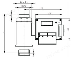
The dimension diagram is as follows: Table 1 shows the flange connection dimensions for PN1.6Mpa, and Table 2 shows the flange connection dimensions for PN0.6Mpa
| Matching type | size | |||||||
| D | K | A | H | d | b | f | 2z-d | |
| DN25 | 115 | 85 | 220 | 270 | 65 | 22 | 1.5 | 4-14 |
| DN40 | 150 | 110 | 248 | 295 | 86 | 24 | 1.5 | 4-18 |
| DN50 | 165 | 125 | 318 | 300 | 100 | 28 | 2 | 4-18 |
| DN80 | 200 | 160 | 318 | 335 | 132 | 28 | 2 | 8-18 |
| DN100 | 220 | 180 | 352 | 362 | 156 | 30 | 2 | 8-18 |
| DN150 | 285 | 240 | 400 | 432 | 205 | 32 | 2 | 8-22 |
| DN200 | 335 | 295 | 416 | 498 | 365 | 35 | 2 | 12-22 |
| DN250 | 405 | 355 | 425 | 562 | 320 | 36.5 | 2 | 12-26 |
Table 1
| Matching type | size | |||||||
| D | K | A | H | d | b | f | 2z-d | |
| DN50 | 140 | 110 | 221 | 225 | 92 | 20 | 2 | 4-14 |
| DN80 | 190 | 150 | 224 | 250 | 128 | 20 | 2 | 4-18 |
| DN100 | 210 | 170 | 293 | 268 | 145 | 23 | 2 | 4-18 |
| DN150 | 265 | 225 | 320 | 298 | 205 | 29 | 2 | 8-18 |
Table 2
install
- The intelligent controller and flow meter (industrial measuring instrument) should be installed coaxially, and the direction of fluid flow should be consistent with the direction indicated on the housing.
- Newly installed or overhauled pipelines must be cleaned before installation
- It should be installed in a location that is easy to maintain, free from strong electromagnetic interference, mechanical vibration, and thermal radiation effects
- Not easy to install in situations with strong pulsating flow or pressure pulsation
- When installing outdoors, there should be a cover on the upper part to prevent rainwater from entering and affecting the service life.
- When using an external power source, there must be a reliable grounding, but the grounding wire must not be shared with the high-voltage system.
- During use, do not change the connection method or arbitrarily twist the various lead interfaces
- For ease of maintenance and without affecting the normal transportation of fluids, please refer to the following schematic diagram during installation.


