VIP member
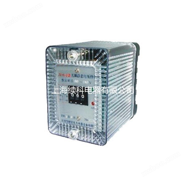
JY8 series integrated circuit voltage relay
JY8 series integrated circuit voltage relay
Product details

DESCRIPTION
JY8 series integrated circuit voltage relay
1、 Purpose:
JY8-31C integrated circuit voltage relay is a static, transient, AC voltage relay. Used in relay protection devices for generators, transformers, and transmission lines, as an action element for overvoltage protection and low-voltage lockout. The relay adopts a digital dial switch, a dedicated switch regulated power supply, and a high-performance intermediate relay to ensure the safety and reliability of the entire machine.
This series of products is an upgraded product designed specifically to replace DY series relays, and those with a setting value above 15V do not require the addition of a DC auxiliary power supply. This product has the advantages of high precision, low power consumption, fast action time, high return coefficient, intuitive and convenient tuning, wide tuning range, and no shaking phenomenon when used as a low voltage. Moreover, the external dimensions and wiring terminals of the relay are identical to those of the DY series, making replacement convenient.
2、 Model Description


3、 Main technical parameters
1. Voltage setting range
a) A: 1V~140V (requires auxiliary DC power supply);
b) B: 15V~130V ;
c) C: 80V~240V ;
d) D: 180V to 440V.
2. Rated auxiliary DC voltage: 48V, 110V, 220V.
3. Power consumption
a) AC circuit power consumption: At the maximum set voltage value, the power consumption of the relay shall not exceed 2.5VA;
b) DC circuit power consumption: Under rated auxiliary DC voltage, the relay power shall not exceed 4W.
4. Allowable range of variation for DC auxiliary voltage: 0.8-1.1 times the rated value.
5. Action time
a) Overvoltage relay: The action time when the setting value is increased from 0.8 times to 1.2 times shall not exceed 25ms.
b) Low voltage relay: The action time when the setting value drops from 2 times to 0.8 times shall not exceed 25ms.
6. Return time
a) Overvoltage relay: When the setting value drops from 1.2 times to 0.8 times, the return time shall not exceed 25ms.
b) Low voltage relay: When the setting value is increased from 0.8 times to 2 times, the return time shall not exceed 25ms.
7. Return coefficient:
a) The return coefficient of overvoltage relay shall not be less than 0.9.
b) The return coefficient of the low-voltage relay is not greater than 1.1.
8. Setting error: Under reference conditions, the voltage setting error shall not exceed 5%.
9. Contact performance:
The relay contacts have a breaking capacity of 50W in a DC inductive load circuit with a voltage not exceeding 250V and a current not exceeding 2A (time constant of 5ms ± 0.75ms), and a breaking capacity of 250VA in an AC circuit with a voltage not exceeding 250V and a current not exceeding 1A (power factor of 0.4 ± 0.1).
10. Insulation resistance
The insulation resistance between the exposed non charged metal parts and the circuits without electrical connection of each relay circuit should not be less than 300M Ω.
11. Dielectric strength
Relay circuits should be able to withstand an AC test voltage of 2kV (effective value) and 50Hz between exposed non-metallic parts, as well as between coil circuits and contact circuits, for a duration of 1 minute. There should be no insulation breakdown or flashover phenomenon.
12. Working conditions
a) The usage location does not allow explosive media, and the surrounding media should not contain gases or conductive media that corrode or damage metals. It is not allowed to be filled with water vapor or have serious mold presence;
b) Strong vibrations and impacts are not allowed in the usage location;
c) The usage location should have equipment to defend against rain, snow, wind, and sand;
d) The usage location does not allow an external magnetic induction intensity exceeding 1.5mT.
13. Electrical anti-interference relays shall comply with GB7261 and GB6261 "Electrical anti-interference tests for static relays and protective devices".
4、 Relay wiring diagram


The contacts in the picture are in a relay inactive state.
5、 Appearance and opening size
The JY8-10 series adopts a protruding fixed structure, and the appearance and installation hole size are detailed in Figure 1.


The JY8-20 series adopts a protruding plug-in structure, and the appearance and installation hole size are detailed in Figure 2.


The JY8-30 series adopts an embedded insertion structure, and the appearance and installation hole size are detailed in Figure 3.


Online inquiry

