
VIP member
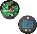
305 series intelligent temperature transmitter circular card
The temperature at the industrial site is input to the 305X through a thermistor or thermocouple sensor, and after analog-to-digital conversion, it is
Product details
Technical Parameter
input
sensor type
305A/B/C/D1: Pt100,Pt1000,Cu50,Cu100
305A/B/C/D2: S,R,B,K,N,E,J,T,WRe3-25
305A/B/C/D3: Pt100,Pt1000,Cu50,Cu100
S,R,B,K,N,E,J,T,WRe3-25
Accept user specifications
Connection method
305A/B/C/D1: A two, three, or four wire heating resistance sensor
305A/B/C/D2: One thermocouple sensor and one thermistor sensor (three wire) are used for cold end compensation, or a fixed cold end temperature is set for compensation without a thermistor sensor. The built-in thermistor sensor of the transmitter can also be used for cold end compensation (the compensation accuracy will affect the final measurement accuracy)
305A/B/C/D3: Adopt the 3051 or 3052 connection method according to the requirements
measuring range
See Appendix 1: List of Input Sensor Types and Accuracy
response time
≤ 250ms with sensor for short circuit and open circuit monitoring
output
Two wire system 4-20mA
HART
Load resistance Ra
Ra ≤ (Us-14.7V)/0.024A, Us is the loop voltage
sensor fault
Short circuit: Accept user specified (3.5~3.75mA)
Open circuit: Accept user specified (21)~23mA)
system failure
Can be set to 3.2mA or 24mA
measurement accuracy
Accuracy (digital measurement accuracy)
See Appendix 1: List of Input Sensor Types and Accuracy
Analog output accuracy
0.025% full scale
Long-term Drift
First year<0.035% full scale
Temperature influence
See Appendix 2: Effects of Environmental Temperature
rated operation conditions
ambient temperature
-40~85℃ -20~60 ℃ (intrinsic safety type)
storage temperature
-40~85℃
electromagnetic compatibility
GB/T 17626, three-level
design
casing
plastics
size
See the figure below
Sensor connection
Display and Control
Display Size
33×23mm
Display digits
5 people
Unit (switchable)
℃ or ℉
set an option
Three buttons on the panel or a HART handheld device and configuration software compatible with the HART protocol
power supply
Loop voltage 15~36V DC
Working current ≤ 3.2mA
Hardware and software requirements
If using a PC to debug and configure the transmitter through HART
hardware
PC with RS232/USB interface
hart modem
software
WidePlus intelligent temperature transmitter testing software
communication
Load for HART connection
250~500Ω
Dual core shielding
≤3km
Multi core shielding
≤1.5km
agreement
HART Protocol 5.2
Transmitter factory settings
damping
0.0S
• Industrial design dimensions that comply with standards
Two wire transmitters based on current loop power supply can effectively reduce wiring costs, lower power consumption, and improve anti-interference capabilities
• HART communication protocol
4-20mA output
When connected to a thermistor sensor, it has short-circuit and open circuit monitoring functions, and when connected to a thermocouple sensor, it has open circuit monitoring functions.
By using the built-in 3 operation buttons in conjunction with a high brightness LCD display, it is easy to set transmitter parameters locally. In addition, remote parameter configuration of the transmitter can be easily achieved through a HART modem.
The rotatable LCD display enhances the flexibility of transmitter installation and can display real-time information such as the percentage of the current measurement to full scale, the current measurement value and its unit, as well as sensor type and transmitter diagnostic information.
• Supports all sensors that comply with IEC751 and IEC584
Online inquiry
-
Contacts
-
Company
-
Telephone
-
Email
-
WeChat
-
Verification Code
-
Message Content
-