
VIP member
Product details
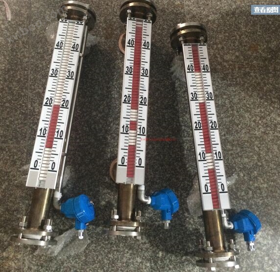
Chlor alkali storage tank level gaugeBasic technical parameters
Measurement range: 300-4000mm (can be specially customized when exceeding 5000mm)
Display accuracy: ± 10mm;
Work pressure: normal pressure
Medium temperature:- 20~200℃;
Medium density: ≥ 0.5g/cm3;
Medium viscosity: ≤ 0.4Pa·S;
Process connection: DN2025/50/80/150 PN1.0 (executing standard HG20592~20635-97), if other standards are required, they can be manufactured according to customer requirements.
Liquid receiving material: F46, etc
(Select according to the chemical properties of the medium and the temperature and pressure of use)

Chlor alkali storage tank level gaugeIt consists of a liquid meter, a chamber, a cylindrical float, a magnetic flap, and a transmitter and alarm switch selected by the user. The liquid level gauge chamber can be regarded as a part of the pressure vessel, connected to the pressure vessel through upper and lower flanges, so that the liquid level changes in the liquid level gauge chamber are consistent with the actual liquid level changes in the pressure vessel. The liquid level signal is transmitted through the magnetic field generated by the magnet in the cylindrical float inside the liquid level gauge chamber. The magnetic flipper displays the liquid level, with red and white flippers evenly arranged in aluminum slots. When the liquid level rises, the magnets inside the red and white flip beads are influenced by the magnets inside the float, driving the flip beads to turn from white to red one by one from bottom to top; When the liquid level drops, the flipping beads turn back from red to white one by one from top to bottom, so that the change in liquid level inside the pressure vessel can be displayed without any power supply. The transmitter or alarm switch uses the magnetic field generated by the float magnet to sample the actual liquid level changes and convert them into standard 4-20mA current output signals or relay output signals. The transmitter is mainly composed of resistors, reed switches, and transmission modules. When the liquid level drives the float to change up and down, the magnetic field generated by the float magnet will cause the suction of the reed switch at the corresponding position in the uniform arrangement, thereby determining the resistance value of the series resistor circuit, and outputting a 4-20mA current signal through the conversion of the transmission module. The alarm switch is mainly composed of a reed switch and a magnet. When the liquid level drives the float to change up and down, the magnetic field generated by the float magnet will cause the corresponding position of the reed switch to be attracted or released, thereby outputting a relay signal. The magnet of the alarm switch enables the output relay signal to have a holding function
| UHZChlor alkali storage tank level gaugeManufacturer number | |||||||||
| Range example: 1-1000mm | Range | ||||||||
| 517C | Ordinary side mounted type | Basic type | |||||||
| SF | Anticorrosive type | ||||||||
| ZQK/DB | Heat tracing type | ||||||||
| D | Frost proof type | ||||||||
| GW | High temperature type | ||||||||
| F | Explosion proof type (Bd is explosion-proof type, Bi is intrinsic safety type) | ||||||||
| DJ | Top mounted type | ||||||||
| GY | High pressure | ||||||||
| GWGY | High temperature and high pressure type | ||||||||
| other | |||||||||
| A | 0.45-0.51 | Medium density (g/cm3) | |||||||
| B | 0.51-0.65 | ||||||||
| C | 0.62-0.75 | ||||||||
| D | 0.75-0.9 | ||||||||
| E | 0.9-1.0 | ||||||||
| F | 1.0-1.8 | ||||||||
| 0 | Atmospheric pressure | Process pressure (MPa) | |||||||
| 1 | Other (specify separately) | ||||||||
| A | 304 | Material | |||||||
| B | 316 | ||||||||
| C | 316L | ||||||||
| D | PVC/UPVC | ||||||||
| E | 304+F4 | ||||||||
| F | 304+PE | ||||||||
| G | other | ||||||||
| A | Column flipping on-site display | Display mode | |||||||
| B | Transmitter output type (field header display) | ||||||||
| C | Transmitter output type (no field header display) | ||||||||
| D | Other types | ||||||||
| A | No alarm point | Alarm code | |||||||
| B | There is an alarm point | ||||||||
| C | There are two alarm points | ||||||||
| D | other | ||||||||
| Example of flange diameter for connection: (DN)50 | Flange diameter | ||||||||

Application instructions for magnetic flap level gauge:
l. Install a shut-off valve between the side mounted level gauge and the upper and lower distribution pipes of the tested container to open or close the level gauge; On the other hand, it brings convenience to the maintenance of liquid level gauges. When the upper and lower shut-off valves are closed, the bottom drain flange of the level gauge can be opened or the drain screw can be removed, and the main body of the level gauge can be cleaned by injecting clean water.
2. When installing a level gauge, the perpendicularity of the flange centerline should be ≤ 4 ‰. When the measurement range of the level gauge is greater than 3 meters, it is necessary to consider adding a reinforced flange (or spider) in the middle as a fixed support to increase strength.
3. The isolation line between the remote liquid level transmitter and the secondary instrument should have a core wire cross-sectional area greater than 0.8mm When laid in parallel with the AC power supply, a distance of at least 20 centimeters should be maintained, and it should be laid separately through iron pipes or with shielded two core cables. The shielding layer can only be grounded at one end.
4. The liquid level controller is selected, and its contact capacity is designed for resistive loads. If non resistive or high-power loads are used, intermediate relays should be used for conversion.
5. It is not advisable to use this level gauge for situations where there are suspended impurities in the liquid medium and magnetic substances, as these impurities can cause blockage in the float component.
6. The blind spot (L1) in the external structure is related to the density of the medium. Therefore, different media have different blind spots.
Installation, use and maintenance:
1. The installation of the liquid level gauge must be vertical to ensure that the float component can move freely up and down inside the main pipe.
2. Magnetic conductors are not allowed to approach the main body of the liquid level gauge, otherwise it will directly affect the accurate operation of the liquid level gauge.
3. After the installation of the liquid level gauge is completed, it needs to be calibrated with magnetic steel to guide the flip column once, so that the display below the zero position is red and the display above the zero position is white.
4. When the liquid level gauge is put into operation, the valve of the lower drainage pipe should be opened first to allow the liquid medium to smoothly enter the main pipe, avoiding the liquid medium from rapidly rising with the floating ball component, which may cause failure and disorderly flipping of the column. If this phenomenon occurs, it can be recalibrated with magnetic steel after the liquid level stabilizes.
5. In order to prevent damage to the float component during transportation, the float component is removed from the main tube of the liquid level gauge before leaving the factory. After the installation of the liquid level gauge is completed, the bottom drain flange is opened, and the float component is reinstalled into the main tube. Note that the heavy end of the float component is facing upwards and cannot be inverted.
Online inquiry
-
Contacts
-
Company
-
Telephone
-
Email
-
WeChat
-
Verification Code
-
Message Content
-