
VIP member
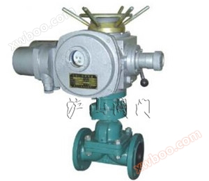
G941W (unlined), G941J (rubber lined) electric diaphragm valve
G941W (unlined), G941J (rubber lined) electric diaphragm valve
Product details
| product name: | Rubber lined electric diaphragm valve | PRODUCT MODEL: | G941W、G941J |
| Drive mode: | electric | Connection form: | flange |
| structural style: | Cut-Through | Sealing material: | Body material, rubber |
| Pressure Range: | 0.6~1.6MPa | Nominal Diameter: | DN15-DN400 |
| Common materials: | Carbon steel, stainless steel | technical advice: |
Introduction to G941W (unlined) and G941J (rubber lined) electric diaphragm valves

Parts list: 1. Valve body 2. Valve body lining 3. Diaphragm 4. Valve disc 5. Lower valve stem 6. Valve cover 7. Cylinder 8. Piston 9. Cylinder head 10. Upper valve stem 11. Handwheel
Design and Manufacturing: GB122239
Structural length: GB12221, JB1688
Flange connection dimensions: GB4216, JB78
1、 G941W (unlined), G941J (rubber lined) electric diaphragm valve usage
Purpose: This valve is designed to control non corrosive or generally corrosive media. The surface of the valve body cavity is unlined or covered with various rubber options, suitable for different working temperatures and fluid pipelines. Applicable temperature: ≤ 85 ℃, ≤ 100 ℃, ≤ 120 ℃, ≤ 150 ℃ (according to lining and diaphragm materials)
Pressure level: PN0.6, 1.0, 1.6
2、 G941W (unlined), G941J (rubber lined) electric diaphragm valve materials
Valve body: cast iron, ductile iron, carbon steel, stainless steel
Valve cover: cast iron, ductile iron, carbon steel, stainless steel
Lining: unlined, rubber
Diaphragm: Rubber
Valve disc: cast iron, carbon steel
Valve stem: carbon steel
Electric device: combination component
3、 G941W (unlined), G941J (rubber lined) electric diaphragm valve testing
Lining layer: Electric spark detection
Testing and inspection shall be conducted in accordance with GB/T13297 standard
Nominal pressure: PN (Mpa) Valve body: PN × 1.5
Sealing: PN × 1.1
4、 Main dimensions and weight of G941W (unlined) and G941J (rubber lined) electric diaphragm valves
|
DN mm |
nominal pressure MPa |
Working pressure MPa |
L (mm) |
D (mm) |
D1 (mm) |
n-φd (mm) |
f (mm) |
h (mm) |
model | Output Torque | Opening and closing time | quality |
| 15 | 0.6 | 0.6 | 125 | 95 | 65 | 4-14 | 2 | |||||
| 20 | 135 | 105 | 75 | 4-14 | 2 | |||||||
| 25 | 145 | 115 | 85 | 4-14 | 2 | 4445 | Z5-18/16 | 50 | 17 | 40 | ||
| 32 | 160 | 140 | 100 | 4-18 | 2 | 457 | Z5-18/16 | 50 | 20 | 42 | ||
| 40 | 180 | 150 | 110 | 4-18 | 3 | 466 | Z5-18/16 | 50 | 14 | 45 | ||
| 50 | 210 | 165 | 125 | 4-18 | 3 | 480 | Z10-18/16 | 50 | 20 | 50 | ||
| 65 | 250 | 185 | 145 | 4-18 | 3 | 517 | Z10-18/16 | 150 | 28 | 60 | ||
| 80 | 300 | 200 | 160 | 4-18 | 3 | 539 | Z10-36/25 | 100 | 16 | 70 | ||
| 100 | 350 | 220 | 180 | 8-18 | 3 | 576 | Z10-36/25 | 100 | 17 | 80 | ||
| 125 | 400 | 250 | 210 | 8-18 | 3 | 634 | Z15-18/25 | 150 | 32 | 104 | ||
| 150 | 460 | 285 | 240 | 8-22 | 3 | 660 | Z15-18/25 | 150 | 53 | 125 | ||
| 200 | 0.4 | 570 | 340 | 295 | 8-22 | 4 | 860 | Z20-18/25 | 200 | 53 | 180 | |
| 250 | 680 | 395 | 350 | 12-22 | 4 | Z20-18/25 | 200 | 53 | 280 | |||
| 300 | 790 | 445 | 400 | 12-22 | 4 | 1003 | Z20-18/25 | 300 | 45 | 434 | ||
| 350 | 900 | 505 | 460 | 16-22 | 4 | ZD30-36a | 300 | 45 | ||||
| 400 | 1000 | 565 | 515 | 16-25 | 4 |
Online inquiry
-
Contacts
-
Company
-
Telephone
-
Email
-
WeChat
-
Verification Code
-
Message Content
-