application application
|

|
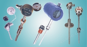
temperature transmitterUsually used in conjunction with display instruments, recording instruments, electronic computers, etc., with an output of 4-20mA. Directly measure the temperature range of -200 ℃ to 1300 ℃ in various production processes
Internal liquid, vapor, and gas media, as well as solid surface temperature.
|
|
characteristic
|
● Two line output of 4-20mA, strong anti-interference ability;
Save the cost of compensating wires and installing temperature transmitters;
● Large measurement range;
Cold end temperature automatic compensation, non-linear correction circuit.
|
|
temperature transmitterWorking principle
|
|
|
Explosion proof thermocouples utilize the principle of gap explosion-proof. When an explosion occurs inside the chamber, it can be extinguished and cooled through the gap between the joint surfaces, preventing the temperature of the flame after the explosion from being transmitted outside the chamber, thus enabling temperature measurement. The thermoelectric potential (resistance) produced by thermocouples (resistors) generates an unbalanced signal through the bridge of a temperature transmitter, which is amplified and converted into a 4-20mA DC electrical signal for the working instrument to display the corresponding temperature value.
|
|
temperature transmitterMain technical parameters
|
|
○ Product execution standards
IEC584
IEC1515
IEC751
JB/T5518-91
JB/T7391-94
○ Temperature measurement range and allowable deviation
● Thermocouple
|
|
|
model
|
Graduation
|
Allowable error and material grade
|
|
Level I
|
class ii
|
|
Allowable deviation
|
Temperature measurement range ℃
|
Allowable deviation
|
Temperature measurement range ℃
|
|
WRNB
|
K
|
±1.5℃
±0.004│t│
|
-40~+375
375~1000
|
±2.5℃
±0.0075│t│
|
-40~+333
333~1200
|
|
WRMB
|
N
|
±1.5℃
±0.004│t│
|
-40~+375
375~1000
|
±2.5℃
±0.0075│t│
|
-40~+333
333~1200
|
|
WREB
|
E
|
±1.5℃
±0.004│t│
|
-40~+375
375~800
|
±1.5℃
±0.004│t│
|
-40~+333
333~900
|
|
WRFB
|
J
|
±1.5℃
±0.004│t│
|
-40~+375
375~750
|
±1.5℃
±0.004│t│
|
-40~+333
333~750
|
|
WRCB
|
T
|
±1.5℃
±0.004│t│
|
-40-~+125
125~350
|
±1℃
±0.0075│t│
|
-40~+333
133~350
|
|
WRPB
|
S
|
±1℃
±[1+0.003(t-1100)]
|
0~+1100
1100~1600
|
±2.5℃
±0.0025│t│
|
0~600
600~1600
|
|
|
● Thermistor
|
|
|
model
|
Graduation
|
Temperature measurement range ℃
|
accuracy class
|
Allowable deviation
|
|
WZPB
|
Pt100
|
-200~+500
|
A-level
|
±(0.15+0.002|t|)
|
|
Grade B
|
±(0.30+0.006|t|)
|
|
WZCB
|
Cu50
Cu100
|
-50~+100
|
-
|
±(0.30+0.005|t|)
|
|
Note: t is the absolute value of the measured temperature of the temperature sensing element
Output signal: 4-20mA, load resistance 250 Ω, transmission wire resistance 100 Ω.
○ Output method: Two line system
○ Accuracy level:
●temperature transmitterAccuracy level: 0.1; 0.2; 0.5;
Display accuracy: Analog indication level 2.5; The number displays a level of 1.0.
○ Power supply: 24V DC±10%
○ Protection level: IP65
○ Explosion proof grade:
Explosion proof form: dIIBT4,dIICT5,dIICT6
Intrinsic safety form: iaIICT6
○ Insulation resistance:
The insulation resistance between the instrument output terminal and the casing should not be less than 50M Ω.
○ Thermal response time:
When there is a step change in temperature, the time required for the current output signal of the instrument to change to 50% of the step change is usually represented by τ 0.5. When the step response stabilization time of the temperature transmitter does not exceed one-fifth of the thermocouple (resistance) thermal response stabilization time τ 0.5, the thermocouple (resistance) thermal response time is used as the thermal response time of the instrument;
When the step response stability time of the temperature transmitter does not exceed half of the thermal response stability time τ 0.5 of the thermocouple (resistance), the thermal response time of the temperature transmitter is used as the thermal response time of the instrument.
○ Basic error
The basic error of the instrument should not exceed the combined error of the basic errors of the thermocouple (resistor) and temperature transmitter.
|
|
temperature transmitterwork environment
|
|
|
Installation site level
|
Temperature ℃
|
Relative humidity%
|
Atmospheric pressure KPa
|
|
Cx1
|
-25~+55
|
5~95
|
86~106
|
|
Cx2
|
-25~+70
|
|
Cx3
|
-40~+80
|
|
○ Determination of support tube length
The working temperature of the temperature transmitter is the sum of the shell temperature rise caused by the support tube and the ambient temperature. The temperature rise of the shell caused by the support tube is shown in the following figure:
|
|
List of Evidence Collection
|
|
|
Explosion proof level
|
Explosion proof certificate number
|
certificate authority
|
|
dⅡB T4
|
GYB97151
|
NEPSI
|
|
dⅡB T4
|
GYB97152
|
NEPSI
|
|
dⅡC T4
|
GYB97203
|
NEPSI
|
|
dⅡB T5
|
GYB97204
|
NEPSI
|
|
iaⅡCT6
|
GYB99412
|
NEPSI
|
|
iaⅡCT6
|
GYB99413
|
NEPSI
|
|
|
Note: NEPSI explosion-proof certification is a national level instrument explosion-proof safety supervision and inspection station
|
|
|
Instrument wiring method
|
|

|
|
Intrinsically Safe Wiring Diagram
|
|
|
|
|
Junction box method
|
|
|
D Ⅱ BT port level
|
D Ⅱ CT oral level
|
|
|
|
|
|
Schematic diagram of the structure of the junction box with display
|
|
|
|
Model naming method
|
|
W
|
Temperature instrument
|
|
|
|
|
|
|
|
|
|
|
|
|
|
|
|
|
|
|
|
|
|
|
|
|
|
|
|
|
|
|
|
|
|
|
|
|
|
|
|
|
|
|
|
|
|
|
|
|
|
|
|
|
category
|
|
R
Z
|
thermocouple
thermal resistance
|
|
|
|
|
|
|
|
|
|
|
|
|
|
|
|
|
|
|
|
|
|
|
|
|
|
|
|
|
|
|
|
|
|
|
|
|
|
|
Index number of temperature sensing element material
|
|
M
N
E
F
C
P
Q
R
|
Nickel chromium silicon nickel silicon N
Nickel chromium nickel silicon K
Nickel chromium copper nickel E
Iron Copper Nickel J
Copper Copper Nickel T
Platinum rhodium 10 platinum S
Platinum rhodium 13 platinum R
Platinum rhodium 30- Platinum 6B
|
P
C
|
Platinum Pt100
Copper Cu50
|
|
|
|
|
|
|
|
|
|
|
|
|
|
|
|
|
|
|
|
|
|
|
|
|
|
|
|
|
B
|
temperature transmitter
|
|
|
|
|
|
|
|
|
|
|
|
|
|
|
|
|
|
|
|
|
|
|
|
|
|
|
|
|
|
|
|
|
|
|
|
|
Installation fixed form
|
|
1
2
3
4
5
6
|
No fixed device
Fixed thread
Movable flange
Flange
Flexible tube connector type
Fixed thread cone form
|
|
|
|
|
|
|
|
|
|
|
|
|
|
|
|
|
|
|
|
Form of junction box
|
|
4
|
explosion-proof type
|
|
|
|
|
|
|
|
|
|
|
|
|
|
|
|
|
Protection tube diameter
|
|
0
1
|
Φ16
Φ12
|
|
|
|
|
|
|
|
|
|
|
|
Workplace format
|
|
G
|
variable cross-section
|
|
|
|
|
|
|
|
|
|
Display mode
|
|
N
S
|
Display without header
Digital display (LCD liquid crystal display)
|
|
|
|
|
|
|
|
|
W
|
R
|
N
|
B
|
--
|
2
|
4
|
0
|
G
|
S
|
|
Typical Model Example
|
|
|
Selection Notice
|
1) Model number
2) Dividing number
3) Temperature range
4) Explosion proof grade
5) Accuracy level of thermocouple (resistor)
6) Accuracy level of temperature transmitter (display)
7) Installation fixed form
8) Material of protective tube
9) Length or insertion depth
Example A: Withtemperature transmitterExplosion proof thermocouple, K-type, fixed thread M27 × 2, explosion-proof grade dIIBT4, temperature transmission range 0-800 ℃, temperature transmitter accuracy grade 0.5, protective tube 316L, length 450mm, insertion depth 300mm. The model is WRNB-240, L=450×300, DIIBT4, temperature transmitter 0.5 level, protective tube 316L, thread M27 × 2, transmission range 0-800 ℃.
|