
VIP member

Sulfuric acid flowmeter, concentrated sulfuric acid pipeline flowmeter
Sulfuric acid flowmeter, concentrated sulfuric acid pipeline flowmeter
Product details
inferiorSulfuric acid flowmeterThe measurement principle is Faraday's law of electromagnetic induction, and the main components of the sensor are: measuring tube, electrode, excitation coil, iron core, and magnetic yoke housing.Sulfuric acid flowmeterMainly used to measure the volumetric flow rate of conductive liquids and slurries in closed pipelines. Including highly corrosive liquids such as acids, alkalis, salts, etc.Sulfuric acid flowmeterWidely used in industries such as petroleum, chemical, metallurgical, textile, food, pharmaceutical, papermaking, as well as environmental protection, municipal management, water conservancy construction, etc.
Integrated intelligent flowmeter
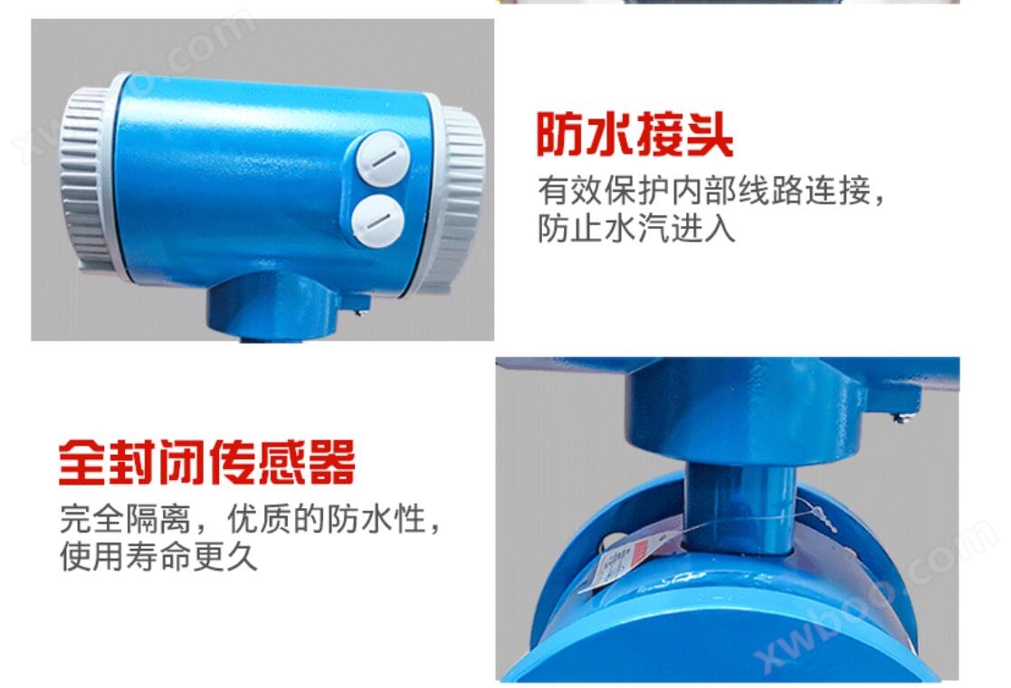
The sensing voltage signal of the sensor is linearly related to the average flow rate, therefore the measurement accuracy is high. The integrated intelligent electromagnetic flowmeter measures the unobstructed flow inside the pipeline, so there is no additional pressure loss; There are no movable parts inside the measuring pipeline, so the sensor has an extremely long lifespan. The integrated intelligent electromagnetic flowmeter requires a shorter straight pipe section, with a length of 5 times the diameter of the pipeline, as the induced voltage signal is formed in the entire space filled with magnetic field and is the average value on the pipeline surface. The sensor part only has the inner lining and electrodes in contact with the measured liquid. As long as the electrode and inner lining materials are selected reasonably, they can be corrosion-resistant and wear-resistant.
Sulfuric acid flowmeterProduct features:
1. Measurement is not affected by changes in fluid density, viscosity, temperature, pressure, and conductivity;
2. There are no obstructing flow components or pressure loss inside the measuring tube, and the requirements for straight pipe sections are relatively low;
3. Series nominal diameter DN6~DN3000. There are multiple options for sensor lining and electrode materials;
4Sulfuric acid flowmeterThe converter adopts a novel excitation method, with low power consumption, stable zero point, and high accuracy. The flow range can reach 1500:1;
5. The converter can be integrated or separated from the sensor;
6. The converter adopts a 16 bit high-performance microprocessor, 2x16 LCD display, convenient parameter setting, and reliable programming;
7. For a bidirectional measurement system, it is equipped with three integrators: forward total, reverse total, and difference total; Can display. Zhuang, reverse flow, and have multiple outputs: current, pulse, digital communication HART;
8. The converter adopts surface mount technology (SMT) and has self checking and self diagnostic functions;
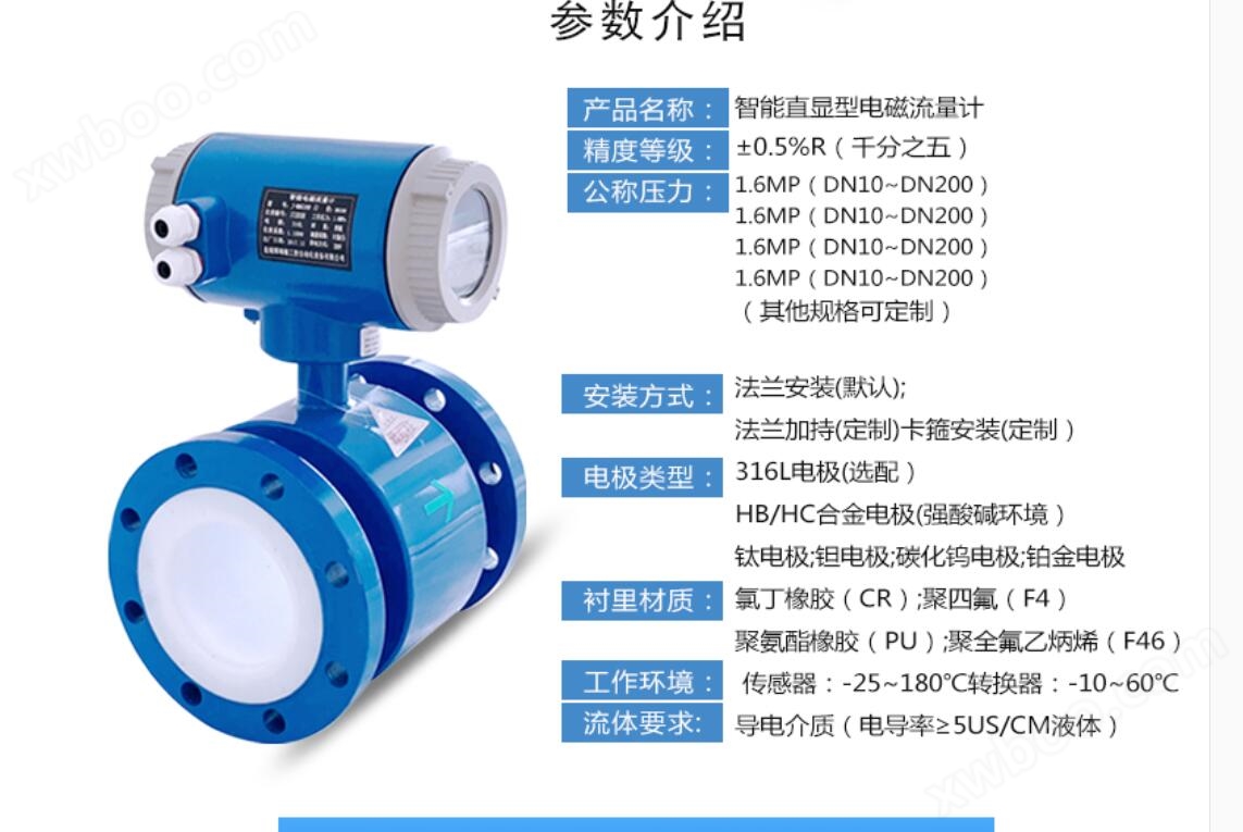
1. Nominal diameter (mm): Pipeline PTFE lining: DN10~DN1200; Pipeline type rubber lining: DN40~DN1200;
2. Flow direction: positive, negative, net flow;
3. Range ratio: 150:1;
4Sulfuric acid flowmeterRepetitive error: ± 0.1% of the measured value;
5. Accuracy level: Pipeline type: 0.5 level, 1.0 level;
6. Temperature of the tested medium: ordinary rubber lining: -20 to+60 ℃; High temperature rubber lining: -20 to+90 ℃; PTFE lining: -30 to+100 ℃; High temperature PTFE lining: - 20~+180℃;
7Sulfuric acid flowmeterRated working pressure: DN6-DN80:≤1.6MPa; DN100-DN250:≤1.0MPa; DN300-DN1200:≤0.6MPa;
8. Flow velocity range: 0.1-15m/s;
9. Conductivity range: The conductivity of the measured fluid is ≥ 5 μ s/cm;
10. Current output: 0-10mA: 0-1.5k Ω; 4~20mA:0~750 kΩ;
11. Digital frequency output: The upper limit of the output frequency can be set within 1-5000Hz with a transistor collector open circuit bidirectional output with photoelectric isolation. When the external power supply is ≤ 35V conducting, the maximum collector current is 250mA;
12. Power supply: AC220V, DC24V or 3.6V battery;
13. Requirement for straight pipe length: upstream ≥ 5DN, downstream ≥ 2DN;
14. Connection method: The flowmeter and piping are connected by flanges, and the flange connection size should comply with the provisions of GB11988;
15. Explosion proof grade: mdIIBT4;
16. Protection level: IP65, Specially customized up to IP68;
17. Environmental temperature: - 25~+60℃;
18. Relative temperature: 5% to 95%;
19. Total power consumption: less than 20W;
Sulfuric acid flowmeterHow to choose correctly:
The selection of instruments is a very important task in instrument applications. Relevant data shows that 2/3 of instrument failures in practical applications are caused by incorrect selection or installation of instruments. Please pay special attention.
◆ Collect data
1. Composition of the tested fluid
2. Maximum and minimum flow rates
3. Maximum work pressure
4. Maximum and minimum temperatures
The tested fluid must have a certain degree of conductivity, with a conductivity>5 μ S/CM
The maximum and minimum flow rates must comply with the numbers in the following table
| Caliber mm | Flow range m3/h | Caliber mm | Flow range m3/h |
| φ15 | 0.0636~6.36 | φ450 | 57.23~5722.65 |
| φ20 | 0.11~11.30 | φ500 | 70.65~7065.00 |
| φ25 | 0.18~17.66 | φ600 | 101.74~10173.6 |
| φ40 | 0.45~45.22 | φ700 | 138.47~13847.4 |
| φ50 | 0.71~70.65 | φ800 | 180.86~18086.4 |
| φ65 | 1.19~119.4 | φ900 | 228.91~22890.6 |
| φ80 | 1.81~180.86 | φ1000 | 406.94~40694.4 |
| φ100 | 2.83~282.60 | φ1200 | 553.90~55389.6 |
| φ150 | 6.36~635.85 | φ1600 | 723.46~72345.6 |
| φ200 | 11.3~1130.4 | φ1800 | 915.62~91562.4 |
| φ250 | 17.66~176.25. | φ2000 | 1130.4~113040.00 |
| φ300 | 25.43~2543.40 | φ2200 | 1367.78~136778.4 |
| φ350 | 34.62~3461.85 | φ2400 | 1627.78~162777.6 |
| φ400 | 45.22~4521.6 | φ2600 | 1910.38~191037.6 |
The maximum and minimum operating temperatures must comply with the temperature requirements specified by the flowmeter.
Determine if there is negative pressure present.
You can choose the corresponding electromagnetic flowmeter based on the flow rate in the table above. If the inner diameter of the selected electromagnetic flowmeter does not match the inner diameter of the current process pipeline, it should be shrunk or expanded.
If the pipeline undergoes shrinkage, consideration should be given to whether the pressure loss caused by shrinkage will affect the process flow.
From the perspective of product price, smaller caliber electromagnetic flow meters can be chosen to relatively reduce investment.
When measuring clean water, the economic flow rate is 1.5-3m/s. When measuring solutions that are prone to crystallization, the flow rate should be appropriately increased to 3-4m/s to achieve self-cleaning and prevent adhesion and sedimentation; When measuring abrasive fluids such as slurry, the flow rate should be appropriately reduced to 1.0-2m/s to reduce wear on the lining and electrode. Actual applications rarely exceed 7m/s, and exceeding 10m/s is even rarer.
Correct wiring
① The excitation cable can use YZ medium-sized rubber sheathed cable, which has the same length as the signal cable
② Signal cables and other power cables must be strictly separated and cannot be laid in the same pipe, parallel, or twisted together. They should be separately threaded in steel pipes.
③ The signal cable and excitation cable should be kept as short as possible, and excess cables should not be coiled together. The excess cables should be cut off and re welded. When the cables enter the sensor electrical interface, they should be made U-shaped at the port to prevent rainwater from penetrating into the sensor.
④Sulfuric acid flowmeterThe connection between the excitation cable and the converter is completed with dedicated wiring, and the converter and external connection are integrated into the electromagnetic flowmeter.
12、 Selection of installation environment:
In order to ensure stable operation of the transmitter, the following requirements should be noted when selecting the installation environment:
1. Try to avoid ferromagnetic objects and specific equipment with strong electromagnetic fields (such as large motors, transformers, etc.) to prevent the magnetic field from affecting the working magnetic field and flow information of the sensor.
2. It should be installed in a dry and ventilated place as much as possible, and should not be installed in damp or water prone areas.
3. Avoid direct sunlight and rain as much as possible, and avoid environments with temperatures above 45 ℃ and relative humidity above 95.9%.
4. Choose a place that is easy to maintain and has convenient activities.
5. The flowmeter should be installed at the rear end of the water pump and must not be installed on the suction side; The valve should be installed on the downstream side of the flowmeter.
13、 Installation requirements for straight pipe sections:
Sensors have certain requirements for the upstream and downstream straight pipe sections of the installation point, otherwise it will affect the measurement accuracy.
1. If there is a tapered pipe upstream of the sensor installation point, there should be an equal diameter straight pipe section of not less than 15D upstream of the sensor and an equal diameter straight pipe section of not less than 5D downstream.
2. If there is a gradually expanding pipe upstream of the sensor installation point, there should be an equal diameter straight pipe section of not less than 18D upstream of the sensor, and an equal diameter straight pipe section of not less than 5D downstream.
3. If there is a 90 ° elbow or lower joint upstream of the sensor installation point, there should be an equal diameter straight pipe section of not less than 20D upstream of the sensor, and an equal diameter straight pipe section of not less than 5D downstream.
4. If there are two 90 ° elbows on the same plane upstream of the sensor installation point, there should be an equal diameter straight pipe section of not less than 25D upstream of the sensor and an equal diameter straight pipe section of not less than 5D downstream.
5. If there are two 90 ° elbows on different planes upstream of the sensor installation point, there should be an equal diameter straight pipe section of not less than 40D upstream of the sensor and an equal diameter straight pipe section of not less than 5D downstream.
6. The flow regulating valve or pressure regulating valve should be installed as much as possible outside 5D downstream of the sensor. If it must be installed upstream of the sensor, there should be an equal diameter straight pipe section of not less than 50D upstream and an equal diameter straight pipe section of not less than 5D downstream.
Particular attention
1. If a valve is installed near the upstream of the sensor installation point, constantly opening and closing the valve will greatly affect the service life of the sensor and easily cause permanent damage to the sensor.
2. Sensors should be avoided as much as possible from being installed on very long overhead pipelines. Over time, the sagging of the sensor can easily cause sealing leakage between the sensor and the flange. If installation is necessary, pipeline fastening devices must be installed at 2D positions upstream and downstream of the sensor.
14、 Installation precautions:
1. The sensor should be installed vertically and the fluid should flow from bottom to top to ensure that the solid and liquid phases are in a mixed state. The reason is that solid objects (such as sediment, small stone particles, etc.) in the medium are prone to precipitation. In addition, if there are fish and weeds in the pipeline, the movement of fish in the pipeline will cause the output of the flowmeter to oscillate back and forth; The back and forth swing of weeds hanging near the electrode can also cause instability in the output of the flowmeter. Install a metal filter at the upstream inlet of the flowmeter to block fish and weeds from entering the measuring tube.
2. Improper setting and operation of the pipeline to prevent negative pressure may cause negative pressure to be generated inside the sensor. When the valves upstream and downstream of the flowmeter are closed simultaneously, if the temperature of the fluid is higher than the air temperature, it will shrink after cooling, which poses a risk of forming negative pressure inside the pipe. Negative pressure causes the lining to peel off from the metal conduit, resulting in electrode leakage.
3. Add a negative pressure prevention valve near the flowmeter, open the valve to connect to atmospheric pressure to prevent negative pressure from being generated inside the sensor. When a vertical pipeline is connected downstream of the flowmeter, if the upstream valve of the flow sensor is used to close or adjust the flow rate, negative pressure will be formed inside the measuring tube of the sensor. To prevent negative pressure, it is necessary to add back pressure or use downstream valves to regulate and close the flow rate.
4. Adequate maintenance space is often required for large-diameter flow meters to be installed in instrument wells for the convenience of pipeline installation, wiring, inspection, and maintenance. For the convenience of observation, wiring, and maintenance, instrument installation should be at a certain height from the ground for easy cleaning and installation.
15、 Troubleshooting:
During operation, various faults may cause inaccurate measurements. Generally, the faults caused by electromagnetic flow meters during operation can be divided into two categories. One type is caused by the malfunction of the flowmeter itself or damage to its components; One type of fault is caused by changes in external conditions, such as unstable output, countless flows, excessive errors, etc. Here are several simple troubleshooting methods:
a、 Unstable output: 1. Unstable flow field; 2. The liquid detected by the sensor contains gas and large solid blocks; 3. Electrical connection virtual connection; 4. Poor grounding; 5. Solution to electrode leakage: 1. Modify the pipeline or install fake sensors; 2. Normal phenomena; 3. Check the wiring and connect the wires properly; 4. Connect the ground wire properly; 5. Repair the sensor.
b、 Liquid flow without output: 1. Reverse the two core wires of the signal transmission cable between the converter and the liquid flow; 2. The power supply is not connected or has poor contact; 3. There is leakage in the sensor instrument pipeline, housing, and end face. Solution: 1. Reverse the wire head; 2. Connect the power supply and maintain good contact; 3. Repair the sensor.
c、 Liquid does not flow but has output: 1. There is a broken circuit in the signal transmission cable connection between the converter and the liquid; 2. The signal cable is disconnected from the electrode connection; 3. Surface contamination or deposition of insulation layer on the electrode; 4. Poor grounding or open circuit. Solution: 1. Connect the cable properly; 2. Open the sensor and reconnect it; 3. Clean the surface of the electrode; 4. Connect the ground wire properly.
d、 Excessive error: 1. Zero point too high; 2. Not completely filled with liquid; 3. Excessive distortion of the power supply; 4. Poor grounding. Solution: 1. Adjust the zero point again; 2. Improve pipeline conditions, with sensors always filled with liquid; 3. Improve the power supply conditions to meet normal working conditions; 4. Connect the ground wire properly.
16、 How to choose correctly:
The selection of instruments is a very important task in instrument applications. Relevant data shows that 2/3 of instrument failures in practical applications are caused by incorrect selection or installation of instruments. Please pay special attention.
1. Collect data:
① Composition of the tested fluid
② Maximum flow rate, minimum flow rate
③ Maximum work pressure
④ Maximum temperature, minimum temperature
2. Range confirmation
The flow rate of the medium measured by the general industrial electromagnetic flowmeter should be 2-4m/s. In special circumstances, the minimum flow rate should not be less than 0.2m/s and the maximum should not be greater than 8m/s. If the medium contains solid particles, the commonly used flow rate should be less than 3m/s to prevent excessive friction between the lining and the electrode; For viscous fluids, the flow velocity can be chosen to be greater than 2m/s. A higher flow velocity helps to automatically eliminate the effect of viscous substances attached to the electrode, which is beneficial for improving measurement accuracy.
Under the condition that the range Q has been determined, the size of the flowmeter diameter D can be determined based on the range of flow velocity V mentioned above, and its value can be calculated by the following formula:
Q=πD2V/4
Q: Flow rate (㎡/h) D: Inner diameter of pipeline V: Flow rate (m/h)
The range Q of the electromagnetic flowmeter should be greater than the expected maximum flow value, while the normal flow value should be slightly greater than 50 of the flowmeter's full-scale scale.
Design selection and ordering instructions:
1. Select the flowmeter correctly based on the measured fluid medium.
2. The tested fluid is selected as ordinary type for non corrosiveness, and corrosion-resistant type for corrosiveness.
3. Please indicate the name, flow rate, pipe diameter, working pressure, temperature, density, viscosity, and other information of the tested medium when placing an order.
4. Select appropriate specifications and varieties based on the measurement range and application scenarios of the fluid being tested.
Online inquiry
-
Contacts
-
Company
-
Telephone
-
Email
-
WeChat
-
Verification Code
-
Message Content
-