
VIP member
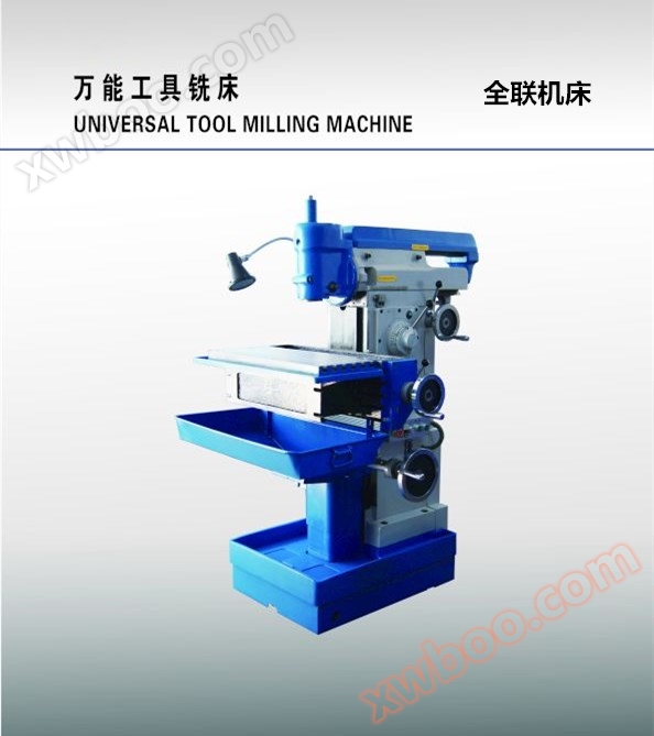
X8126 Universal Tool Milling Machine
Introduction - X8126 Universal Tool Milling Machine is a widely used machine tool that is suitable for processing various complex small parts such as
Product details
X8126 universal tool milling machine is a widely used machine tool, which is suitable for processing various complex small parts such as cutting tools, fixtures, stamping dies, and pressure molds. With the help of various special accessories, it can complete the processing of spiral, arc, rack, gear, spline and other parts.
This machine tool has a horizontal spindle, a vertical spindle, a horizontal worktable (which can be installed in three different positions), a vertical worktable, and can also be equipped with special accessories such as a universal angle table, a circular worktable, plugs, indexing heads, flat pliers, etc., to complete various machining tasks, making it very versatile.
1、 Main specifications and parameters of the machine tool
1. Horizontal workbench
Workbench area (length)X width) (mm)...... 700 x 280
Horizontal spindle centerline to First installation location35-385mm
Distance from the workbenchSecond installation location42-392mm
Third installation location132-482mm
Longitudinal travel of workbench(mm). ...............................350
Workbench lifting stroke(mm). ...............................350
Workbench feed level... 8 poles
Vertical and vertical feed range of workbench.................25-285mm/min
Workbench vertical and vertical rapid movement speed.................1000mm/min
T型槽数............................................6槽
T-shaped groove width (mm)
T-groove spacing (mm)
2. Vertical workbench
Workbench area(Length x Width) (mm)...... 750x260
T型槽数...............................................5槽
T-shaped width (mm) 14
T-groove spacing (mm)
3. Horizontal spindle
Spindle taper hole taper X8126Mo'sNo. 4
Lateral movement stroke of the spindle body(mm) . ...............................200
The movement of the dial per revolution(mm). ..............................1.5
Spindle speed level8 poles
Main spindle speed range...............................110-1230r/min
Spindle feed rate series8 poles
Spindle feed rate circumference................................25-285mm/min
4. Vertical spindle
Spindle taper hole taperX8126....................Mo'sNo. 4#
Manual axial movement of the spindle(mm). ..............................80
The movement of each grid on the dial(mm) . ..............................0.5
Spindle rotation angle......................................+ -45o
Spindle speed series 8 poles
Main spindle speed range...............................150-1660r/min
2、 Main dimensions between components
Distance between the centerline of the horizontal main axis and the lower plane of the upper beam(mm). .................96
Distance between the centerline of the horizontal spindle and the plane on the horizontal worktable(mm). .......35-385
If installed in the third position, the flat surface of the horizontal workbench can also be lowered97mm)
The distance between the edge of the horizontal workbench and the front plane of the vertical guide rail of the bed due to different installation positions(mm). .........212-412
The distance between the centerline of the vertical spindle and the front plane of the vertical guide rail of the bed body(mm). ............155
The distance between the lower end face of the vertical spindle and the plane on the horizontal worktable(mm). ............0-285
(Horizontal workbench installed in the first and second ways)
Power parameters, external dimensions, weight
Total power capacity (kVA) ...................................4
Main motor power(kw). ...........................................3
Main motor speed(r/min). ...................................1430
Cooling water pump motor(w). ..........................................40w
Machine tool dimensions (length)X width x height) (mm)...... 1450x1445x1650
machine toolnet Heavy gross weight(kg). ............(X8126、XS8126) (X8126A、XS8126A)
3、 Machine toolknotIntroduction to Structure
This machine tool mainly consists of a bed body, a horizontal spindle body, a vertical spindle body, a lifting table, a vertical worktable, a horizontal worktable, a gearbox, a feed box, a vertical spindle body loading and unloading mechanism, a transmission and variable speed operating mechanism, and electrical, lubrication, and cooling systems.
1. Bed frame
The bed body is a box shaped casting structure with reasonable internal reinforcement and sufficient strength and stiffness. It is a fundamental supporting component for lifting platforms, gearboxes, horizontal spindle bodies, and other components.
There is a vertical guide rail in front of it for installing the lifting platform; There are two square windows in the middle of the bed, one for installing the main gearbox and the feed gearbox, and the other for installing the electrical cabinet; The upper top surface has guide rails for installing the horizontal spindle body; The rear of the machine tool is the installation site for sprockets, pulleys, overload safety protection devices, electromagnetic clutches, etc., and protective covers are installed here. There is a stopper installed on the side of the bed to adjust and limit the vertical movement distance of the lifting platform.
The lower part of the bed is the base, which is connected as a whole with bolts. The base serves as the support for the entire machine tool, the front part is the machine tool coolant storage tank, and the cooling pump is installed on it. The rear part is the installation ground for the main motor and its bracket.
2. Horizontal spindle body
The horizontal spindle body is installed on the upper guide rail of the bed through a guide rail, and can move horizontally along the matching guide rail. It is equipped with a horizontal spindle, lead screw, etc., and an upper beam is installed on the upper part.
The two ends of the horizontal spindle are installed on the support seat with high-precision rolling bearings, ensuring the accuracy and rigidity of the machine tool during processing. The front end of the horizontal spindle is equipped with a tapered hole, which can be used to install various machining tools. The cutting tool is fixed in the spindle taper hole with a pull rod. The front end face of the horizontal spindle is also equipped with a concave slot for connecting the vertical spindle body. A gear is installed on the horizontal spindle to receive the rotational motion of the main transmission system.
The screw is used to receive the feed motion transmitted by the feed system, provide power for the forward and backward movement of the horizontal spindle body, and achieve the purpose of moving the horizontal spindle forward and backward.
The upper beam is connected to the horizontal spindle body through a guide rail, which can move forward and backward along the direction of the guide rail. There is a hanging bracket on the upper beam, which serves as a support for the tool holder when it is used in the horizontal spindle taper hole, improving the rigidity of the tool holder and increasing machining accuracy.
The horizontal spindle body is equipped with a stopper for adjusting and limiting the forward and backward movement position.
3. Vertical spindle body
The vertical spindle body is connected to the horizontal spindle body end face by bolts, and it contains the vertical spindle, sleeve, gear, and protrusion.
The two ends of the vertical spindle are installed in a sleeve through high-precision rolling bearings, allowing for rotational motion within the sleeve while ensuring machining accuracy and rigidity; The front end of the vertical spindle is equipped with a tapered hole for installing machining tools. The machining tool is fixed in the spindle taper hole by a pull rod. Its rotational motion is obtained by connecting the convex block provided at the input end of the vertical spindle internal transmission chain with the groove provided at the front end of the horizontal spindle.
The sleeve is installed in the vertical spindle hole through precise fitting, and can be moved up and down along its axis by an external operating handle. The vertical spindle body can rotate around the centerline of the horizontal spindle by+-45OTurn around.
4. Lift platform
The lifting platform provides support for the vertical workbench and ensures the up and down and longitudinal movement of the workbench.
The lifting platform is connected to the vertical guide rail in front of the bed through a guide rail. The control box is equipped with a gear reversing mechanism, which can be operated by an external reversing handle (cross handle) to control its up and down movement along the guide rail on the bed, while also controlling the longitudinal movement of the worktable. The size of the up and down movement distance can be adjusted through two speed rails. The vertical movement distance of the workbench is adjusted by the two collision blocks installed on it.
The motion of the feed system is input by the light rod installed on the control box of the lifting platform, and through the reversing mechanism, it drives the screw on it to rotate. The screw nut fixed on the support converts it into a linear motion of the screw up and down, driving the lifting platform to move up and down. The upward or downward movement is obtained by the reversing mechanism.
5. Vertical and horizontal workbenches
The vertical workbench is connected to the lifting platform guide rail through a guide rail, and can be driven by a screw to move longitudinally along the lifting platform guide rail. Vertical workbench is used for installing horizontal workbench, processing workpieces, or related accessories to expand the processing range. It is equipped with two stop irons at the bottom, which are used to adjust and limit the size of its movement stroke.
The horizontal workbench is installed on the vertical workbench with bolts, used for installing processed workpieces and accessories. There are three installation positions available for the horizontal workbench to adapt to the requirements of different workpiece processing (see figure for different installation methods)1-2).
By using the reversing mechanism of the lifting platform, the worktable can also achieve longitudinal and different directional movements.
6. Main gearbox and feed gearbox
The main gearbox is installed in the middle window of the bed for the purpose of spindle speed change. Externally, it consists of a variable speed control panel and handle, speed indicator, speed plate, etc. When shifting gears, first pull the operating handle towards yourself, then turn the handle. When the indicator is aligned with the selected speed, push the handle into place. When shifting gears, the machine should be stopped. The feed gearbox is set to obtain different feed speeds and installed in the middle window of the lower bed of the main gearbox. The external composition of the feed gearbox is similar to that of the main gearbox, and the operation method is the same, except that the speed pointer and speed plate are changed to indicate the feed rate.
There is a plunger pump installed inside the feed box, which provides lubrication for the main gearbox and various moving parts inside the feed box. The oil supply of the plunger pump is observed through the oil window. The plunger pump is equipped with an oil filter at the suction end of the oil inlet pipe.
7. Machine tool cooling system
The cooling pump is directly driven by the motor to suck out the coolant, which is then injected through a plastic tube and a metal hose. By rotating the control valve nozzle, the flow rate of the coolant can be controlled or turned off. After being used, the coolant is filtered through the horizontal workbench water tank and the water receiving tray, and then returned to the base water tank for recycling.

Manufacturer direct sales of various types of machine equipment, including milling machines, vertical milling machines, horizontal milling machines, lifting table milling machines, gantry milling machines, single column milling machines, single arm milling machines, turret milling machines, drilling milling machines, instrument milling machines, tool milling machines, universal milling machines, universal tool milling machines, end face milling machines, CNC milling machines, etc.
Consultation and ordering hotline:
Xi'an Quanlian Machine Tool Special Recommendation:www.cncql.com
Online inquiry
-
Contacts
-
Company
-
Telephone
-
Email
-
WeChat
-
Verification Code
-
Message Content
-